Construction Rules:
- The numbers along the borders indicate how many cargo containers (boxes in each cargo hold
 ) are in each row/column
 - Connectors:
 (one pipe) cannot connect to
  (two pipes), but
  (universal) can connect to either.
 - Some pieces have been welded
 together and must be placed next to each other
 - The final ship should have no exposed connectors (every connector joins with another piece)
- No component connects to another component of the same type (the starting cabin
 can connect to crew cabins
  )
) - Engines
 and cannons
 must have their output pointed at the exterior of the blueprint
 - Every crew cabin is connected to at least one cargo hold (and vice versa)
- Full connector rules are available on page 5 of the game manual (only needed if the rules above don’t make sense)
Step 1
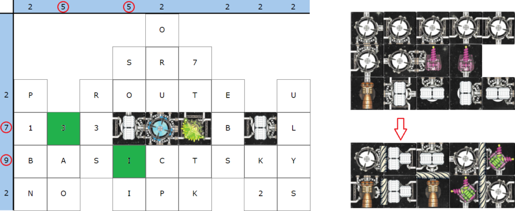
From the above starting position, we can observe that there are 4 odd numbers in the rows and columns that indicate the number of cargo containers (rule 1). Since there are only two cargo holds with an odd number of containers, they must be placed at the intersections of the odd rows/columns. Since one of those intersections is already occupied by a starting cargo hold, the other two must be at locations 3 and I. Since both 3-container cargo holds are welded to other pieces, we can determine that the one welded to the engine must be placed over position I using rule 4 (no exposed connectors) as placing this pair over position 3 would have an exposed connector at the left edge. This means that the other cargo hold with the attached crew cabin must be placed over position 3.
Step 2
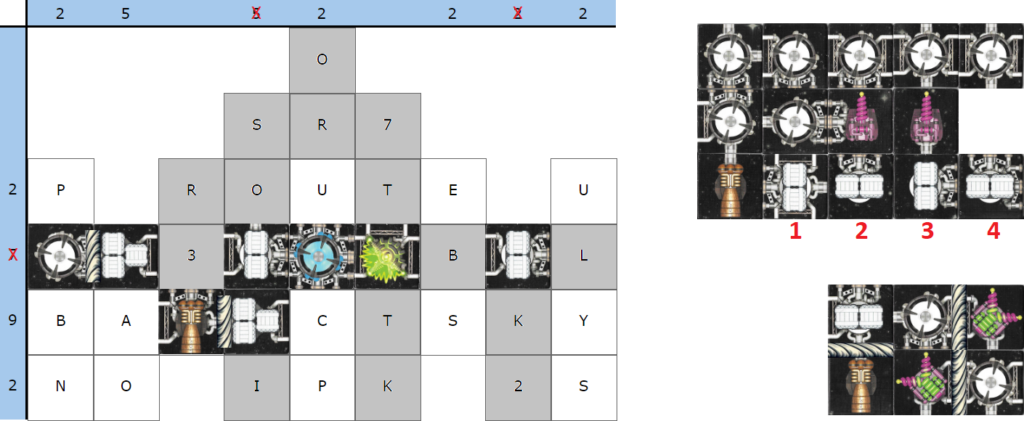
At this point, focusing on the remaining cargo holds, there is one that is welded to an engine. By rule 6, the engine must be pointed at the exterior of the blueprint so it must go in either the bottom row or S in row 5. However, attempting to place the engine in columns 1, 2, 6, 7, or 8 causes the attached cargo hold to break the connector rules (rule 2). Attempting to place the engine in column 5 breaks rule 5 (no like components can connect) as it would connect two cargo holds. This only leaves the bottom right corner of the blueprint for it to fit in column 9. For the remaining 4 cargo holds, starting with the second column, we must place a hold over either O or A to satisfy rule 1. Placing hold 3 over A would block off access to the rest of the bottom-left corner which still needs to have a cargo container, so the cargo hold must go over the O. Hold 2 must go over the O (as the other options all have a right-facing connector). This also limits hold 3 to being placed over the B in column 1 as that column still needs a container and the others have left-facing connectors. Since column 5 still needs a container as well, the only place one will fit is over the U and it must be hold 1 to make a valid connection to the piece below. This means that hold 4 must be placed over the S in column 7 to satisfy the remaining numerical constraints.
Step 3
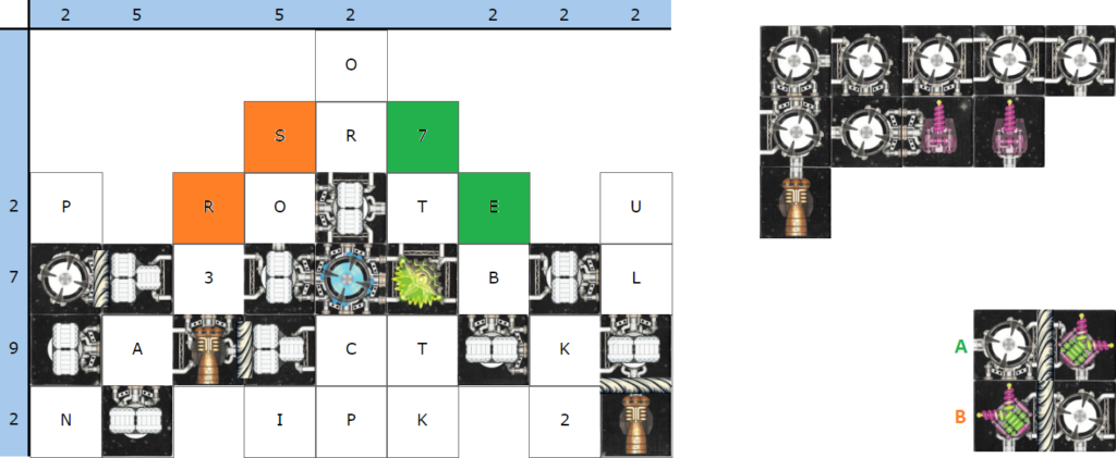
Now that all of the cargo holds have been locked in position, the two remaining welded pairs jump out as having the most restricted placement. Since rule 6 states that all cannons must have their output pointed at the exterior of the blueprint, this means that there are only two possible placements for either double cannon (S or R for the cannon facing left/up, 7 or E for the cannon facing right/up). Due to the welded cabin attached to the left/up cannon, it cannot be placed at S as the cabin would violate the connector rules with the cargo hold in the middle column. Therefore, the pair of pieces can only fit over R/O. Locking in the placement for the other double cannon takes one extra step as it requires disproving a placement. If we attempt to place the right/up cannon over the 7, this places the crew cabin over the R in column 5 with a single pipe connector facing left. Looking at the remaining components, there is nothing left that could legally fit over the S without violating other rules. Therefore, the only legal placement option for the pair is over T/E.
Step 4
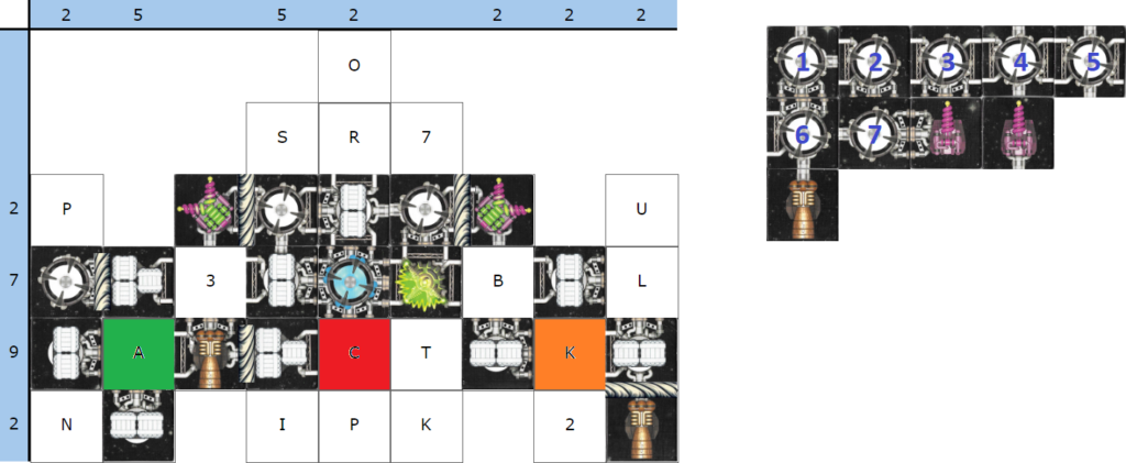
Now that the pool of components has been trimmed down and many positions have been locked in, we can leverage rule 7 (all crew cabins are connected to a cargo hold and vice versa) to help place some crew cabins. At this point, we can observe that positions A and C must contain a crew cabin in order to satisfy this requirement as the cargo holds are attempting to connect to these squares and still need a connected cabin. For position A, cabin 3 is the only option with connectors that fit. For position C, cabins 4-6 have connectors that could work. However, if cabin 4 or cabin 5 are placed at position C, it would require a piece to be placed to the right. If we examine the remaining pieces, there is nothing left in the pool that could go here without violating other rules. Therefore, cabin 6 is the only fit for position C. Finally, if we bring our focus to position K, we can see that it requires a piece with connectors to the left and right with no connector on top. The only piece left in the pool that meets these requirements (since we already placed cabin 3), is cabin 7 so it must go to position K.
Step 5
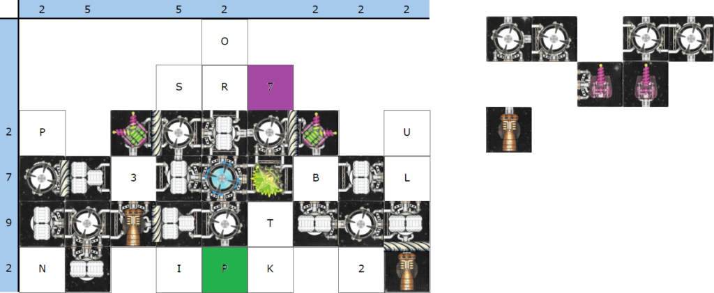
From here, we can quickly lock in the final engine as there’s only one place left that it can fit to satisfy rule 6, position P. We can also identify that there’s a single valid placement for the cannon with the left-facing connector, position 7.
Step 6
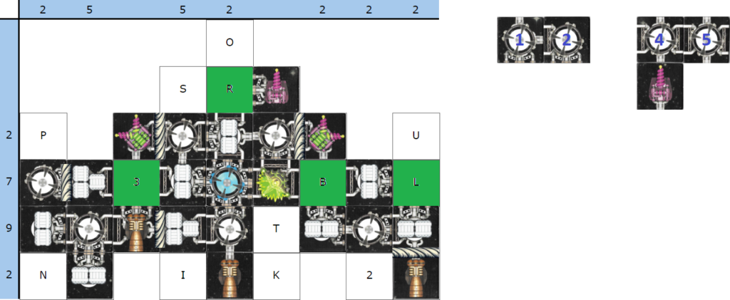
Finally, we’re left with gaps in the ship at positions R, 3, B, and L as highlighted above. With the remaining cabins, the only possible fits are cabins 4/5 at positions 3/B, cabin 1 at position R, and cabin 2 at position L. This just leaves the final cannon which easily slots into the nose position to complete the ship!
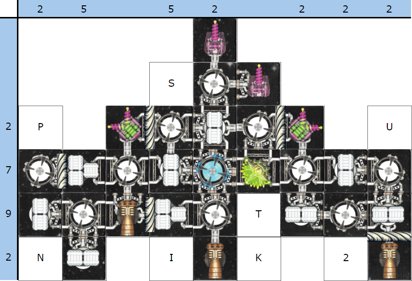
Hopefully you enjoyed this puzzle. It was a lot more work than expected to construct while juggling keeping the solution unique, logical, and within difficulty for the Puzzle Safari event.